Power Electric Wires Thermal Scan

Electrical Panel – MCC Room A
Power Distribution Wires and Terminals
EP-WIRE-BANK-01
Kerina Epperly
August 4, 2025 at 4:45:00 PM
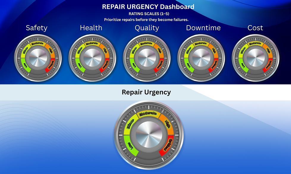
4.00
1.00
2.00
2.00
2.00
2.29


Moderate – localized thermal degradation and failure over time


Localized hotspot at wire-to-terminal contact areas; vertical gradient down the conductor length. L1-L3 most pronounced, PE and T1 moderate; lower contacts show minor or no rise.
Significant heat signatures observed at terminal blocks L1, L2, and L3, as well as neutral (N) and PE (ground). Colors range from yellow-red to white at contact points.
Moderate – localized thermal degradation and failure over time

1.) Loose or oxidized terminal connections
2.) Uneven torque at terminal screws
3.) Load imbalance across phases
4.) Undersized conductor or faulty lug/crimp
1.) Overheating at contact points
2.) No known tripped breakers, but load imbalance or resistance may be developing
3.) No audible buzzing or burning smell reported
4.) Risk of insulation degradation due to temperature rise
1.) Use thermal scanner at different loads to compare trends
2.) Conduct torque checks at terminal blocks
3.) Use clamp meter to validate current load per phase
4.) Visually inspect for oxidation, discoloration, or arc marks
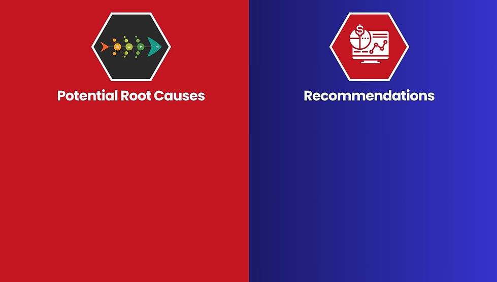
1.) Immediately retorque and re-terminate connections (lockout/tagout required)
2.) Clean contact surfaces if oxidation is present
3.) Rebalance loads if asymmetry is confirmed
4.) Log this panel in thermal scan route for monthly trending
Thermal resistance caused by poor surface contact at terminal connections.

Report Controls:
This Filter controls the main report above.
Instructions:
1.) Click on the Reset button to display all reports.
2.) Select the report you are interested in by clicking in the table on the report.
3.) Click on the Filter button to update the main report.
Title | Component | Inspection Date | Signs and Symptoms | Thermal Visual Cue | Likely Issue | Thermal Image Upload |
|---|---|---|---|---|---|---|
Power Electric Wires Thermal Scan | Power Distribution Wires and Terminals | 04/08/2025 | 1.) Overheating at contact points
2.) No known tripped breakers, but load imbalance or resistance may be developing
3.) No audible buzzing or burning smell reported
4.) Risk of insulation degradation due to temperature rise | Significant heat signatures observed at terminal blocks L1, L2, and L3, as well as neutral (N) and PE (ground). Colors range from yellow-red to white at contact points. | 1.) Loose or oxidized terminal connections
2.) Uneven torque at terminal screws
3.) Load imbalance across phases
4.) Undersized conductor or faulty lug/crimp |
This is your Project description. Provide a brief summary to help visitors understand the context and background of your work. Click on "Edit Text" or double click on the text box to start.