
Ultrasonic Testing
Mechanical / Non-Destructive Testing (NDT)
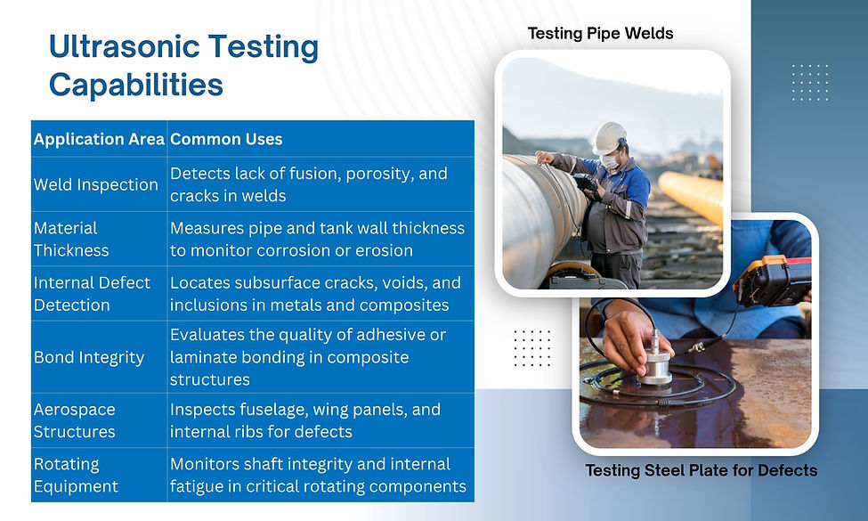
Ultrasonic Testing (UT) is a non-destructive testing method that uses high-frequency sound waves to detect internal flaws, material thickness, or discontinuities in components. Commonly used in manufacturing, aerospace, energy, and infrastructure, UT enables early fault detection by identifying cracks, voids, or corrosion beneath the surface, making it invaluable for inspecting welds, pressure vessels, pipelines, and structural parts without causing damage.

Detection
.jpg)
Common Use Cases
Flaw Detection in Metals & Welds
Identifying cracks, voids, porosity, or lack of fusion in welds.
Detecting fatigue cracks in structural members.Thickness Measurement
Checking pipe walls, tanks, and pressure vessels for corrosion or erosion.
Measuring remaining wall thickness without cutting or dismantling.Bond Integrity Checks
Inspecting composite materials for delaminations.
Verifying adhesive bonds in aerospace, automotive, or manufacturing applications.High-Value or Safety-Critical Components
Turbine blades, aircraft fuselages, bridges, and load-bearing machine parts.
Components where failure could cause catastrophic damage or safety hazards.After Repairs or Modifications
Confirming weld repairs meet specification before returning equipment to service.
Verifying no hidden defects remain after re-machining.When Other NDT Methods Aren’t Practical
When magnetic particle testing isn’t possible due to non-ferrous material.
When X-ray is too expensive, slow, or presents radiation safety issues.
Ultrasonic Testing is used in various applications and industries to:
1.) Detect internal and surface defects such as cracks, voids, inclusions, porosity, and laminations
2.) Measure material thickness in components, structures, or vessels
3.) Characterize material properties such as grain structure, sound velocity, and acoustic impedance
4.) Assess weld quality, integrity, and fusion in welded joints
5.) Conduct preventive maintenance inspections to identify defects before they lead to failure
6.) Monitor manufacturing processes and identify sources of defects or quality issues.
Capabilties
1.) Detects internal cracks, voids, and inclusions not visible on the surface
2.) Measures material thickness with high accuracy
3.) Inspects weld quality, pipe wall thinning, and bonded interfaces
4.) Works on metals, composites, plastics, and ceramics
5.) Allows real-time analysis with digital signal output
6.) Can be automated for inline inspection
7.) Minimal part preparation required
8.) Phased array systems provide detailed 3D views

Limitations
1.) Requires experienced personnel to interpret results correctly
2.) Surface must allow for good sound transmission (needs couplant)
3.) Not ideal for rough, small, or complex geometries
4.) Can be limited in detecting very small flaws near the surface
5.) Interpretation errors may occur due to false echoes or signal noise
6.) Less effective in porous or coarse-grained materials (e.g., cast iron)
7.) Setup can be time-consuming for irregular parts

.jpg)
Personnel conducting Ultrasonic Testing as part of NDT require specialized training in UT techniques, inspection procedures, equipment operation, defect recognition, safety precautions, and relevant industry standards. Training programs cover theoretical knowledge, practical application, interpretation of test results, and certification requirements.
Personnel conducting Ultrasonic Testing as part of NDT may obtain certifications such as:
Ultrasonic Testing Level I, II, or III (UT)
Certification from recognized industry bodies (e.g., ASNT, BINDT, NAS410)
.jpg)
Ultrasonic Testing involves the following steps:
1.) Ultrasonic Wave Generation: A transducer generates high-frequency ultrasonic waves, typically in the range of 0.5 MHz to 25 MHz.
2.) Wave Propagation: The ultrasonic waves are introduced into the material being inspected through a coupling medium such as water, gel, or oil.
3.) Reflection and Refraction: The ultrasonic waves encounter interfaces, defects, or material boundaries within the material. Some waves reflect back to the transducer, while others continue to propagate through the material.
4.) Wave Detection: A receiver transducer detects the reflected waves and converts them into electrical signals.
5.) Signal Analysis: The received signals are analyzed to identify indications of defects, measure material thickness, or assess material properties.
6.) Data Interpretation: The signals are interpreted to determine the presence, size, location, and nature of defects or irregularities.
1.) Ultrasonic flaw detector
2.) Couplant gel or medium
3.) Transducers (contact, angle beam, or immersion)
4.) Phased array UT instruments
5.) Thickness gauges
6.) Data visualization software